Here are days 5 and 6 on the lift install. I will explain the noteworthy points in between each picture.
This first picture shows one of the the rebars that has been bent 90 degrees, epoxied into the existing garage floor, and tied into the lift slab.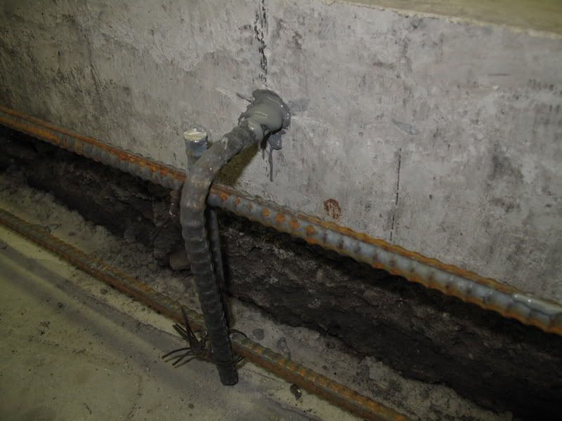 This picture shows the epoxied rebar from the existing floor being tied into the rebar from the recently poured lift slab, together with two complete encircled rebars that will all be inside the sidewall.
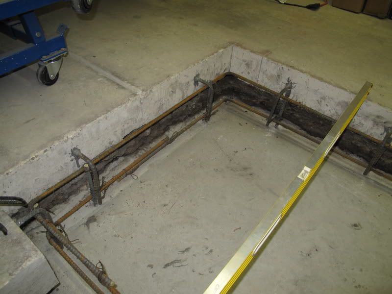 This picture shows the two, 2 inch schedule 80 conduit tubes coming out of the 2 x 12 inch concrete form.
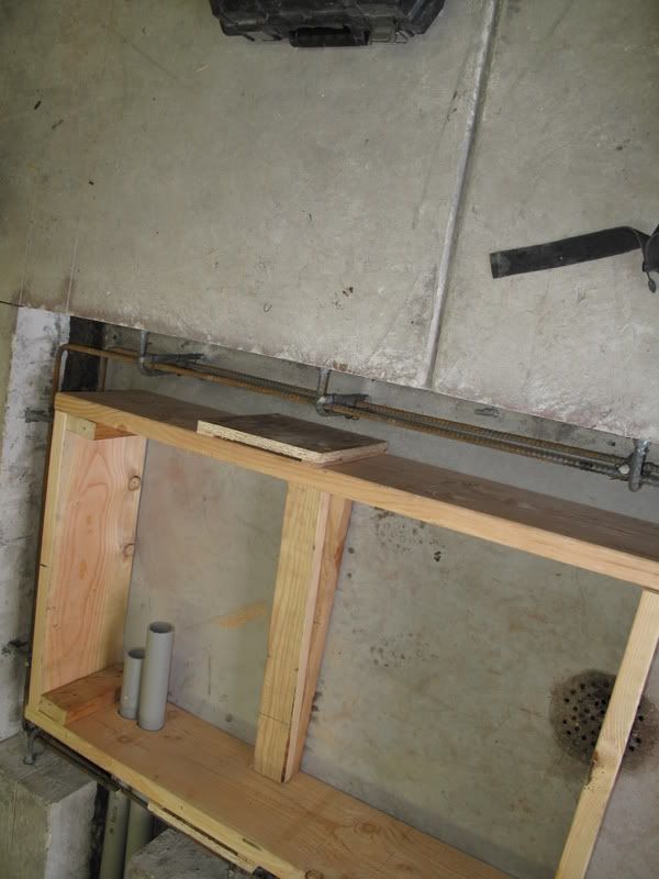 Here is the entire frame built to hold the concrete for the walls and conduit run. Note the protruding piece of wood into the concrete sidewall to make room for the lift front drop support and hinges. The height of the concrete walls are approximately 10 7/16 inch. The 2 x 12s were ripped to accomodate the slightly uneven garage floor so when the concrete is poured to the top of the 2 x 12s, the walls will be level with the perfectly level lift once it is installed.
 Here is the back of the 2 x 12 inch form. Note the 1 1/2 x 1 inch piece of wood attached to the rear 2 x 12 form to allow the protruding lift ramp to fit into the space being created so the rear lift top can (and will) be snug to the back wall.
 Here the installers are mixing and pouring 6 bag concrete into the frame.
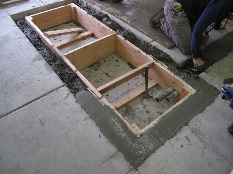 The concrete is all poured and wet.
 Here is a picture of the distance from the steel fabricated frame to the top of the new sidewall. Note it is 7 3/4 inches, which is the height of the 1500 pound Handy electric hydraulic lift in the down position. Also note the cavity in the back wall for the protruding ramp support on the lift.
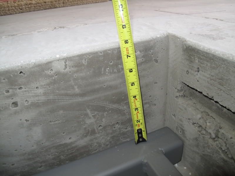 Here is a picture of the lift ramp that protrudes back 1 inch from the lift that the cavity in the concrete was built to house so the top of the lift in the rear can be flush with the rear sidewall.
 This is how the steel frame that will hold the lift looks in the completed concrete hole. You can see the indent in the concrete walls to accommodate the front lift dropdown hinge support. In addition to the extra room the top hinge needs in the sidewall, at the base of the lift on the pan directly under the hinge, there is a pivot shaft that protrudes 1 inch from the pan, whcih is the location of the "front scissor" support point that raises and lowers the lift.
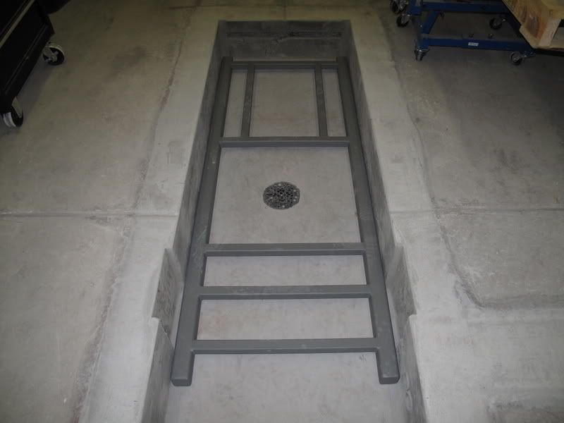 Here is a close up of the hinge support that protrudes out from the lift.
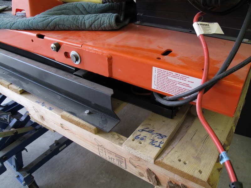 This is a close up of the front lift hinge cut out in the concrete. You can see I also put a 1 1/2 x 1 1/2 inch steel tube cross support piece on the fabricated frame directly under the pivot shaft that protrudes from the pan of the lift. This steel cross piece is also the location, in the center of the lift pan, that the hydraulic cylinder unit is mounted onto the lift pan, which is directly on top if this steel tube cross support.
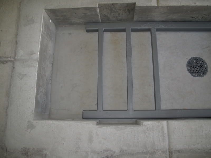 You can see from the steel frame support that the conduit lines come out in front of the fabricated steel frame support. The conduit lines were designed to come out between the base of the lift that houses the electric motor and hydraulic fluid reservoir and the top platform of the lift.
 Close up of the two 2 inch conduit lines.
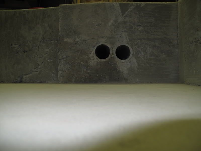
When the lift is installed, I made the countersunk hole five additional inches longer at the front. I intend to put a steel plate, 1/4 inch thick supported by two or three solid blocks of wood (5 x 5 x 10 3/8 inches) or I might use several 4 inch square steel tubes to support the steel plate so it is flush with the garage floor when the lift is in the down position.
I wanted some extra room in front so I could service the lift motor and hydraulic fluid in the event one day I pushed the lift controller button to raise the lift and it does not move. Moreover, I want room to put my lift controller under the steel plate because the cable line that operates it needs to be extended by about 40 inches if it is to be put in the conduit run and hung on the garage wall. If I choose not to extend the lift controller cable, I can put the lift controller in a watertight bag or container under the steel plate in front of the lift, and everything will be at or below garage floor level.
The final step is to let the concrete walls cure a few days then call my friend with his crane and set the lift in the countersunk hole at which time this project will be done.
Randall


 Author
Topic: Pics of my new Handy lift (Read 55255 times)
Author
Topic: Pics of my new Handy lift (Read 55255 times)